
Barber Colman GYZJ Barcol Impressor - Operation and Calibration
 |
 |
 |
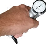
| Simply exert alight pressure against the instrument to drive the spring-loaded indenter point into the material. | See the typical readings of aluminum alloys and review the approximate conversion curves for the barcol impressor models. | Follow the step by step calibration procedure for the Barcol Impressor. Use the included tool to begin the procedure. |
| View Operation | View Conversion | View Calibration |
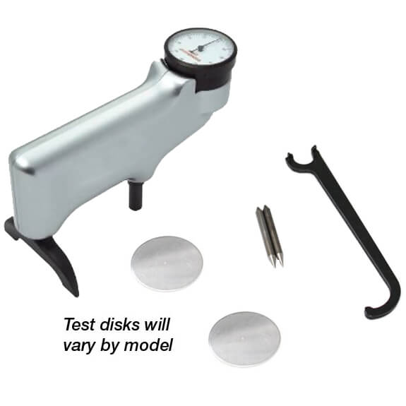
The Impressor is intended for handheld testing of hardness for aluminum and aluminum alloys, soft metals, plastics, fiberglass, rubber and leather. Harder materials cannot be tested with the Impressor. For information on the available models, refer to the current revision of our product guide.
| To test a surface, place the indenter point and the leg of the impressor on the same plane of the surface. To insure reading accuracy, make certain that no indentations from previous use are within 1/16th of an inch of the present indenter point position. Readings should not be taken on both sides of the 1/32nd inch-thick test disks. Readings taken on top of old indentations will adversely affect the accuracy of the reading. An ample supply of appropriate test disks should be maintained for these reasons. |
 |
Press down firmly, but carefully, on the impressor handle. Observe the indicator, noting the peak reading. For softer materials there will be some falling-off of the reading from the peak value. This is normal and is due to the nature of the materials being tested.
As a general rule, you should increase the number of readings taken as the softness of the materials being tested increases. Refer to the table below for recommended minimal numbers of readings for various materials using the Model GYZJ 934-1. Though specific numbers for Models GYZJ 935 and GYZJ 936 are not included due to correlation difficulties with softer materials, the numbers suggested for reinforced plastics serve as a starting point for softer materials.
The indenter point must always be perpendicular to the surface being tested. To maintain perpendicularity, the leg of the Impressor must be on the same plane as the indenter point, with both flats of the leg touching the same surface. Irregularlyshaped objects to be tested should be mounted in a holding jig to assure that perpendicularity is maintained. For flat objects, a temporary offset of the leg to accommodate the thickness of the part being tested can be obtained by placement of washers of appropriate thickness between the leg and the case of the impressor. Without perpendicularity, accuracy of the reading cannot be assured.
![]() Recommended numbers of readings for Model GYZJ 934-1
Recommended numbers of readings for Model GYZJ 934-1
| Reading Range | Number of Readings | Average Variance of | |
| Homogeneous Material | 20 | 9 | 0.28 |
| 30 | 8 | 0.28 | |
| 40 | 7 | 0.28 | |
| 50 | 6 | 0.28 | |
| 60 | 5 | 0.28 | |
| 70 | 4 | 0.28 | |
| 80 | 3 | 0.28 | |
| Reinforced Plastics | 30 | 29 | 0.77 |
| 40 | 22 | 0.78 | |
| 50 | 16 | 0.75 | |
| 60 | 10 | 0.78 | |
| 70 | 5 | 0.75 |
![]() Typical Readings of Aluminum Alloys
Typical Readings of Aluminum Alloys
| Alloy and Temper: | 1100-0 | 3003-0 | 3003H14 | 2024-0 |
| GYZJ-934-1 Reading: | 35 | 42 | 56 | 60 |
| Alloy and Temper: | 5052-0 | 5052H14 | 6061T6 | 2024T3 |
| GYZJ-934-1 Reading: | 62 | 75 | 80 | 85 |
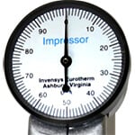
Approximate Conversion Curves for GYZJ-934-1 Approximate Conversion Chart for GYZJ-934-1 to Brinnell, Vickers and Rockwell |
|
![]()
| 934-1 | Brinnell | Vickers | Rockwell | |||
| B | E | F | H | |||
| 35 | 23 | 32 | ||||
| 36 | 23 | 33 | ||||
| 37 | 24 | 37 | ||||
| 38 | 24 | 40 | ||||
| 39 | 25 | 43 | ||||
| 40 | 25 | 25 | 45 | |||
| 41 | 26 | 26 | 47 | |||
| 42 | 26 | 27 | 49 | |||
| 43 | 27 | 27 | 52 | |||
| 44 | 27 | 28 | 54 | |||
| 45 | 27 | 20 | 56 | |||
| 46 | 28 | 30 | 58 | |||
| 47 | 29 | 32 | 24 | 61 | ||
| 48 | 30 | 33 | 25 | 63 | ||
| 49 | 31 | 34 | 28 | 64 | ||
| 50 | 32 | 35 | 30 | 66 | ||
| 51 | 33 | 36 | 33 | 68 | ||
| 52 | 34 | 38 | 36 | 70 | ||
| 53 | 35 | 39 | 39 | 29 | 72 | |
| 54 | 37 | 41 | 42 | 33 | 73 | |
| 55 | 38 | 42 | 44 | 38 | 75 | |
| 56 | 39 | 44 | 46 | 40 | 76 | |
| 57 | 40 | 45 | 48 | 43 | 78 | |
| 58 | 42 | 47 | 51 | 47 | 80 | |
| 59 | 44 | 48 | 53 | 49 | 81 | |
| 60 | 45 | 49 | 55 | 51 | 83 | |
| 61 | 47 | 51 | 57 | 54 | 84 | |
| 62 | 48 | 53 | 59 | 56 | 86 | |
| 63 | 50 | 55 | 62 | 58 | 88 | |
| 64 | 52 | 57 | 64 | 61 | 89 | |
| 64 | 54 | 58 | 65 | 63 | 90 | |
| 66 | 55 | 60 | 67 | 65 | 91 | |
| 67 | 58 | 62 | 69 | 67 | 92 | |
| 68 | 60 | 64 | 71 | 69 | 94 | |
| 69 | 62 | 67 | 73 | 71 | 95 | |
| 70 | 64 | 69 | 18 | 74 | 73 | 96 |
| 71 | 67 | 72 | 19 | 76 | 75 | 98 |
| 72 | 69 | 74 | 28 | 77 | 77 | 99 |
| 73 | 71 | 76 | 33 | 79 | 79 | 100 |
| 74 | 73 | 81 | 39 | 81 | 81 | 101 |
| 75 | 76 | 85 | 45 | 83 | 83 | 102 |
| 76 | 80 | 88 | 48 | 84 | 84 | 103 |
| 77 | 84 | 92 | 52 | 86 | 86 | 104 |
| 78 | 87 | 95 | 56 | 88 | 87 | 105 |
| 79 | 90 | 99 | 60 | 89 | 88 | 106 |
| 80 | 94 | 103 | 63 | 90 | 89 | 107 |
| 81 | 97 | 108 | 65 | 91 | 90 | 108 |
| 82 | 100 | 111 | 69 | 92 | 91 | 108 |
| 83 | 105 | 116 | 72 | 94 | 92 | 109 |
| 84 | 109 | 122 | 75 | 95 | 93 | 109 |
| 85 | 113 | 127 | 77 | 96 | 94 | 110 |
| 86 | 117 | 133 | 80 | 97 | 95 | 111 |
| 87 | 122 | 137 | 83 | 98 | 96 | 111 |
| 88 | 126 | 142 | 86 | 99 | 97 | 112 |
| 89 | 131 | 144 | 89 | 100 | 97 | 112 |
| 90 | 135 | 91 | 101 | 98 | 113 | |
| 91 | 139 | 102 | 99 | 113 | ||
| 92 | 145 | 103 | 100 | |||
| 93 | 103 | 101 | ||||
| 94 | 104 | 101 | ||||
| 95 | 104 | 102 | ||||
| 96 | 105 | 102 | ||||
| 97 | 106 | 103 | ||||
| 98 | 107 | |||||
| 99 | 108 | |||||
| 100 | 108 | |||||
![]()
Approximate Conversion Chart for GYZJ-935 and GYZJ-936 to Type D Durameter
| Type D Durameter | Type D Durameter | ||||
| GYZJ-935 & GYZJ-936 | GYZJ-935 | GYZJ-936 | GYZJ-935 & GYZJ-936 | GYZJ-935 | GYZJ-936 |
| 4 | 64 | 52 | 18 | 67 | 56 |
| 6 | 65 | 52 | 20 | 68 | 56 |
| 8 | 65 | 53 | 22 | 68 | 57 |
| 10 | 65 | 53 | 24 | 68 | 58 |
| 12 | 66 | 54 | 26 | 69 | 58 |
| 14 | 66 | 54 | 28 | 69 | 59 |
| 16 | 67 | 55 | |||
![]()
| Shore (Type) D Durameter | Shore (Type) D Durameter | ||||
| GYZJ-935 & GYZJ-936 | GYZJ-935 | GYZJ-936 | GYZJ-935 & GYZJ-936 | GYZJ-935 | GYZJ-936 |
| 30 | 70 | 60 | 44 | 74 | 65 |
| 32 | 70 | 60 | 46 | 74 | 66 |
| 34 | 71 | 61 | 48 | 75 | 67 |
| 36 | 71 | 62 | 50 | 75 | 68 |
| 38 | 72 | 63 | 52 | 76 | 69 |
| 40 | 73 | 64 | 54 | 77 | 70 |
| 42 | 73 | 64 | 56 | 71 | |
![]()
| Shore (Type) D Durameter | Shore (Type) D Durameter | ||||
| GYZJ-935 & GYZJ-936 | GYZJ-935 | GYZJ-936 | GYZJ-935 & GYZJ-936 | GYZJ-935 | GYZJ-936 |
| 58 | 78 | 72 | 74 | 84 | 80 |
| 60 | 79 | 73 | 76 | 85 | 81 |
| 62 | 79 | 74 | 78 | 85 | 83 |
| 64 | 80 | 75 | 80 | 86 | 84 |
| 66 | 81 | 76 | 82 | 87 | 85 |
| 68 | 82 | 77 | 84 | 88 | 86 |
| 70 | 82 | 78 | 86 | 89 | 87 |
| 72 | 83 | 79 | 88 | N/A | 89 |
For the GYZJ-934-1
|
 |
For the GYZJ-935 and GYZJ-936
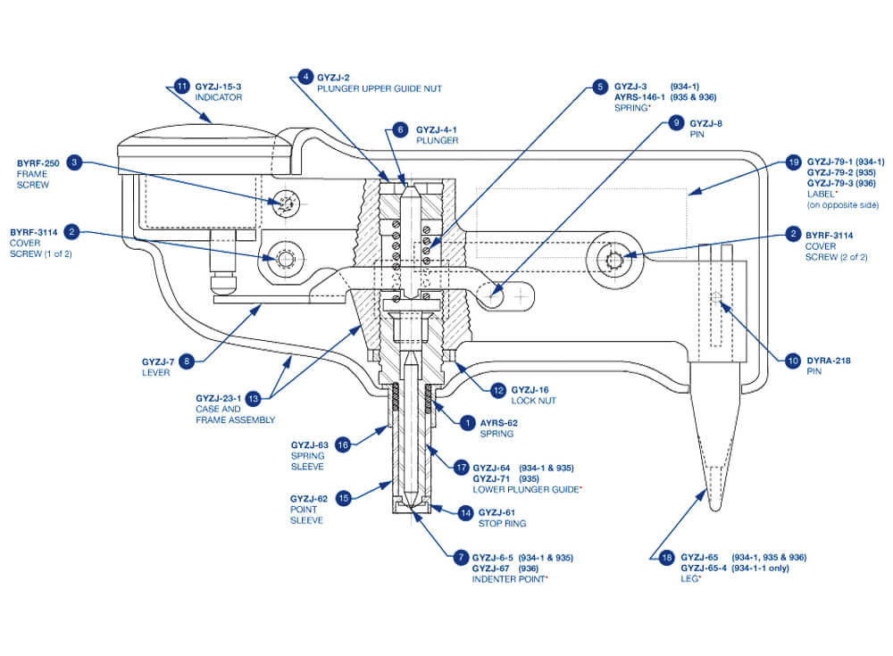
- Set the top adjustment nut about even with the top of the frame.
- Calibrate against the test disk using the bottom adjustment nut (#12 Plunger Lock Nut).
21 Waterway Avenue
Suite 300
The Woodlands, TX 77380
U.S.A.
Tel: 1-281-516-9292
Fax: 1-866-234-0451
E-Mail: info@abqindustrial.net